115 Volt Compressor Wiring Diagram
Higginbotham on thursday, february 14th, 2019 in category wiring diagram. If your motor just has two 14 guage wires a white and a black, i would think it was a 110 instead of a 220.
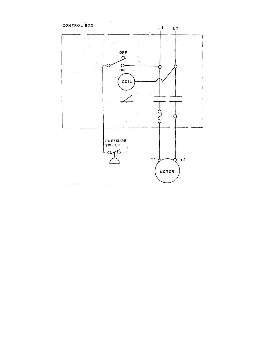
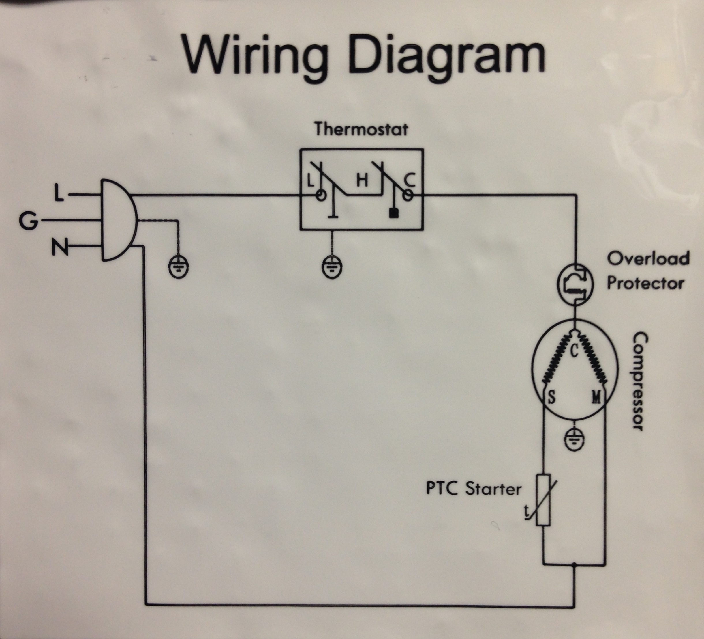
Figure 14. Wiring diagram 115V ac operation.
Baldor motor capacitor wiring diagram a novice s overview of circuit diagrams.

115 volt compressor wiring diagram. Just follow the wires from the plug to the motor like you would with an electric laundry dryer, or other such 3 phase wired equipment. Each part should be placed and connected with different parts in specific way. The compressor oil must be replaced.
This method will work for any pump that runs directly off of a pressure. The red and the back are both hot (110 each) and the green is the ground. It contains instructions and diagrams for various kinds of wiring techniques as well as other products like lights, windows, and so on.
6000 btu 8000 btu 10000 btu 12000 btu. M52 series components list item part number (115 volt) part description no. How to wire a 115 volt electrical outlet.
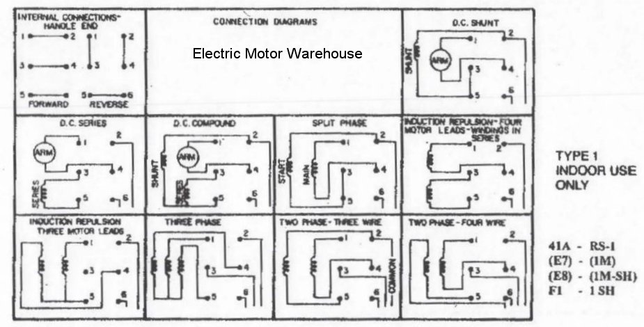
A standard wall outlet carries 120 volts, so most window and portable units will run off the outlet. It here 115 volt without control voltage transformer 115vac single phase to a 115 volt starter coil with a 115 230v 115 230 single phase contactor, air compressor 115v wiring schematic mitchell 1 has added color air brake diagrams to tractor Electrical wiring diagrams terminal pin orientation 3 electrical components use only new electrical components specific for this compressor model.
The dedicated neutral requires an insulated conductor which runs directly to the panel. Then just change out each wire one at. Literally a circuit is the course that enables electrical.
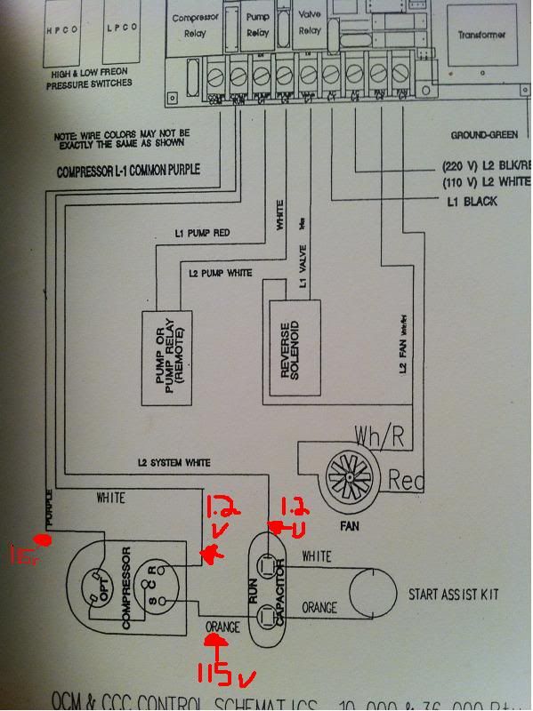
Generally, you have 3 wires going to the motor for ac. 3 phase (3 wire w/gnd) fan control circuit from unit 115v. Technical data compressor model designation conf.
Free wiring diagrams for heating, air conditioning, refrigeration, water heaters, electrical and electric motors. If the compressor requires a start capacitor it is designed to be mounted on the protective cover. In this video, we show you the best way to a pressure switch for 115v and 230v pumps.
August 1, 2021 on baldor single phase 230v motor wiring diagram. Most 220 volt compressor motors have three wires.a red, a black , and a green. Diagram 230 115 volt motor wiring full version hd quality 230v schematic electric doityourself com community forums doerr lr22132 century ac volts menulisitukerjaaku emerson help changing voltage sds of single phase motors on popscreen t35028e practical machinist largest manufacturing technology forum the web how to wire a baldor cat no l1406t.
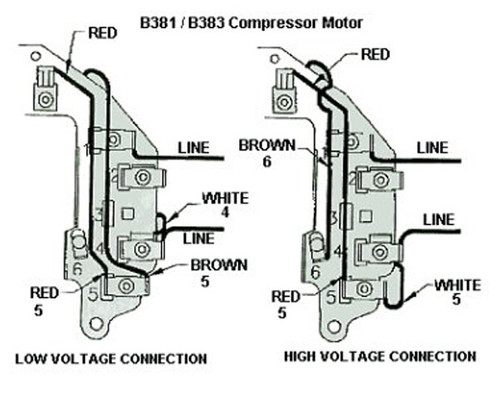
Then connect the brown motor lead to the terminal appropriate for the line voltage being used with the motor. If not, the arrangement won't function as it should be. This guide even contains suggestions for additional provides that you might require to be able to finish your projects.
The 110/220 conversion is very easy to do, but locating all of the information below was Baldor fdl3514m 1 5hp 1ph 115 230v tefc farm duty electric motor in 2020 electric motor electricity industrial electric. A hot, a neutral, and a ground.
Arealighting1 5500 range control switch # 2. Never break a vacuum with air and always change the driers when opening the system for component replacement. 115 volt single speed motor wiring :
Line 1 line 2 ground. See also fractional compressor wiring: Improperly installed and grounded field wiring poses fire &.
A transformer can be used to provide 115v control circuit. Each component should be placed and connected with other parts in specific way. If not, the arrangement won't function as it ought to be.
Use two (2) washer head screws to attach the capacitor mounting bracket to the protective cover.
Wiring Diagram For Compressor Motor
Compressor Wiring Diagram Pdf schematic and wiring diagram
115 230 Volt Century Electric Motor Wiring Diagram Wiring View and Schematics Diagram

Viair Compressor Pressure Switch Relay Wiring Diagram Complete Wiring Schemas
115v AC wiring help. With diagram

33 Century Ac Motor Wiring Diagram 115 230 Volts Diagram Example Database
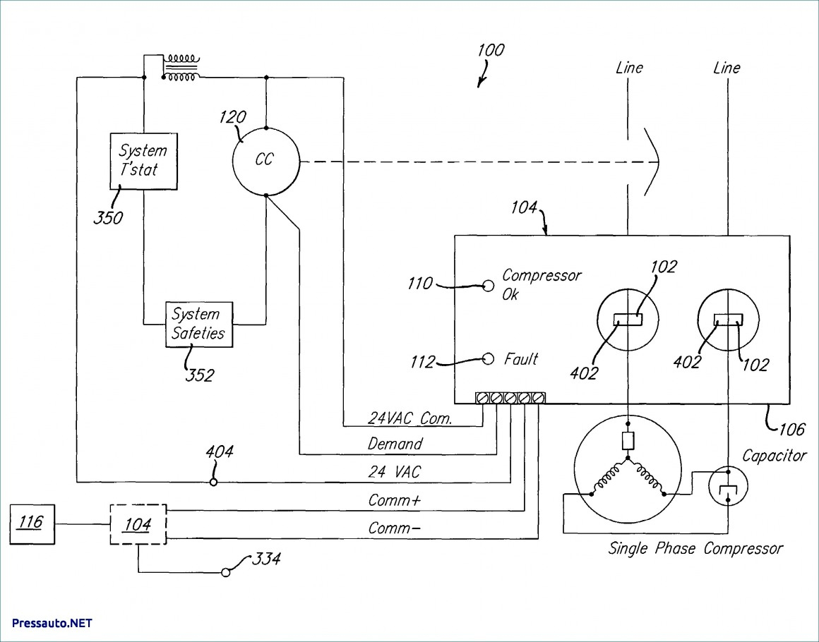
Compressor Wiring Diagram Single Phase CASSANDRALANDER

Wiring Diagram For Freezer 115 Volt schematic and wiring diagram

115 Volt Air Pressor Motor Wiring Diagram Wiring Diagram Database
115 Volt Motor Wiring Diagram


115 230 Volt Century Electric Motor Wiring Diagram Wiring View and Schematics Diagram
115 230 Volt Electric Motor Wiring Diagram Wiring Diagram

115/230 Volt Motor Wiring Diagram Database Wiring Diagram Sample
New Build Electronics Newb Diagram Help fridgebuild BrewPi Community

33 Century Ac Motor Wiring Diagram 115 230 Volts Diagram Example Database
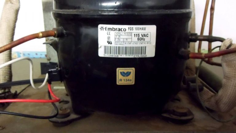
How To Wire In A Rc0210 Hard Start Kit On A 115 Volt Embraco Embraco Compressor Wiring

Wiring Diagram For Freezer 115 Volt schematic and wiring diagram
Baldor Wiring Diagram 115 230 Wiring Library

60 Luxury Simple Electric Motor Wiring Diagram Pics Wsmce Emerson Electric Motors Wiring